Maintain a Constant Orientation
In this lab, I used PID CONTROL to maintain the car in set orientation. For the first part, I implemented a controller maintaining a constant orientation even when the robot is kicked. For the second part, the car was able to move forward until a new orientation, such as 180 degrees, was sent, then turning and driving towards that direction. Here are the process and details of my experiment.
Parts Required
1 x R/C stunt car
1 x SparkFun RedBoard Artemis Nano
1 x USB cable
2 x Li-Ion 3.7V 400 mAh (or more) battery
2 x Dual motor driver
2 x 4m ToF sensor
1 x 9DOF IMU sensor
1 x Qwiic connector
Part1: Stationary Car
Debugging Data
To get the data feedback, I created a struct named debugData,
storing the setpoint, current roll angle, angle error, timestamp and the motor offset.
struct debugData{
    int setpoint;
    float angle_roll;
    float error;
    unsigned long timestamp;
    int motor_offset;
};
The size of the debugData is 16 bytes. A debugDate array is used to record all the information.
Here, the array size is 1000 and will take up 16 kB memory.
const int MAX_DATA_SIZE=1000;
debugData datas[MAX_DATA_SIZE];
Bluetooth Commands
As shown in below, I created several Bluetooth commands to conrtol the robot.
enum CommandTypes
{
    BEGIN,
    STOP,
    SEND_P,
    SEND_GOAL,
    GET_ARRAY,
    PING,
};
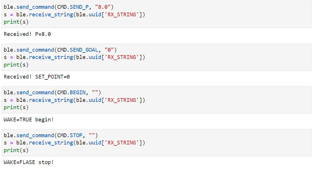
The robot controller will start and stop once BEGIN and STOP commands are sent to the Artemis over Bluetooth.
KP value is able to change by the executing ble.send_command(CMD.SEND_P, "1"), so that I can update the gains without reprograming the Artemis.
Similarly, SEND_GOAL is used to set the orientation.
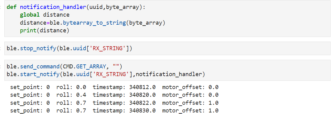
GET_ARRAY, function write_data() will be called
and start to send debugging datas to the computer.
Thanks for the ESTRING.h, the recorded datas can be converted into ESTRING datatype and be sent over bluetooth.
Here is the related code.
write_data()
{

    for(int i=0; i < datas_index; i++){
        tx_estring_value.clear();
        tx_estring_value.append(" setpoint: ");
        tx_estring_value.append(datas[i].setpoint);tx_estring_value.append(" ");
        tx_estring_value.append(" roll: ");
        tx_estring_value.append(datas[i].angle_roll);tx_estring_value.append(" ");
        tx_estring_value.append(" error ");
        tx_estring_value.append(datas[i].error);tx_estring_value.append(" ");
        tx_estring_value.append(" timestamp: ");
        tx_estring_value.append(float(datas[i].timestamp));tx_estring_value.append(" ");
        tx_estring_value.append(" motor_offset: ");
        tx_estring_value.append(float(datas[i].motor_offset));tx_estring_value.append(" ");
        tx_characteristic_string.writeValue(tx_estring_value.c_str());
    }
}
PID control
I implemented the PID control in the main loop.
Once the BEGIN command is sent the PID control will begin.
The Artemis will get the gyroscope data, calculate the roll angle and motor offset if the IMU sensor data are ready.
Otherwise, it will just skip all those things.
if(WAKE && datas_index < MAX_DATA_SIZE){
    if (myICM.dataReady()){

        // get angle(roll) from the gyro and time
        myICM.getAGMT();
        datas[datas_index].timestamp=millis();
        if(datas_index!=0){
            float dt;
            dt=(float)(datas[datas_index].timestamp-datas[datas_index-1].timestamp)*0.001;
            float wx;
            wx=myICM.gyrX();
            datas[datas_index].angle_roll=datas[datas_index-1].angle_roll+wx*dt;
        }
        else{
            datas[datas_index].angle_roll=0;
        }

        // Using PID to control the motors
        datas[datas_index].setpoint=SETPOINT;
        float error;
        error=datas[datas_index].angle_roll-SETPOINT;
        int motor_offset;
        motor_offset=P_value*error;
        if(abs(motor_offset)>255)
            motor_offset=255*(motor_offset/abs(motor_offset));
        datas[datas_index].motor_offset=motor_offset;

        motor_control(motor_offset);

        datas_index++;


    }


}
Part2: Mobile Car
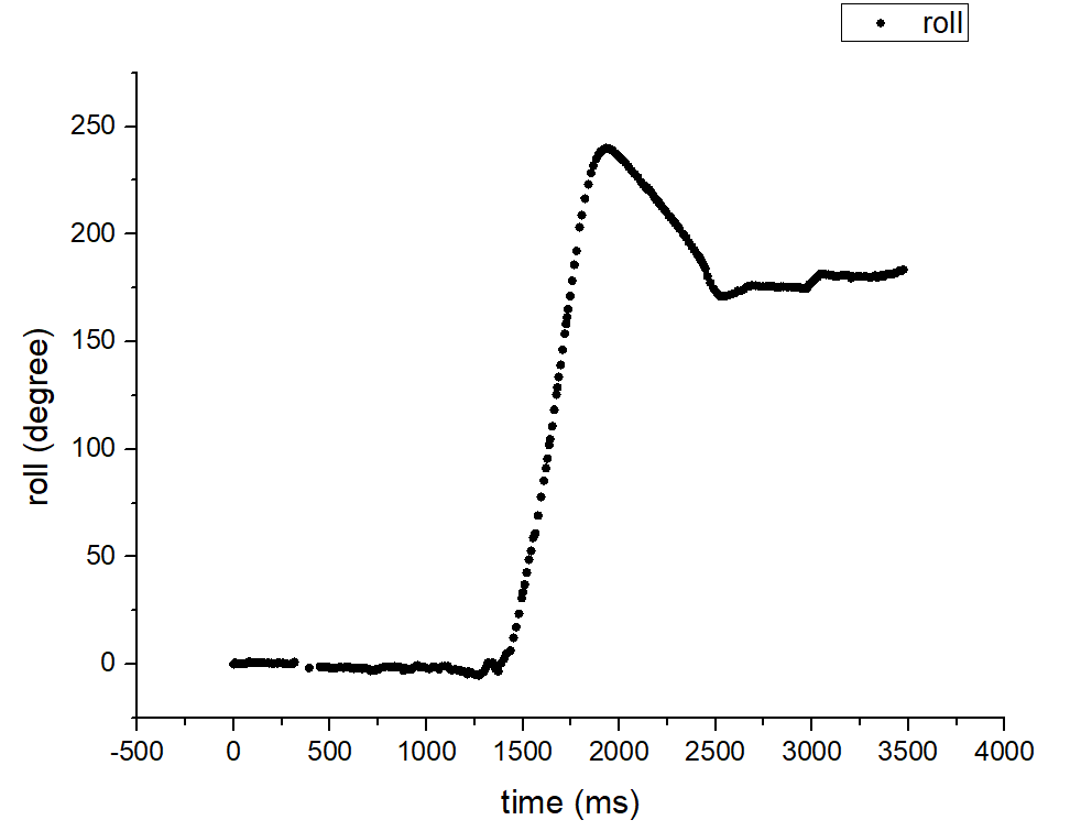
In this part, the car is going to move forward until a new orientation is sent, then turning and driving towards that direction.
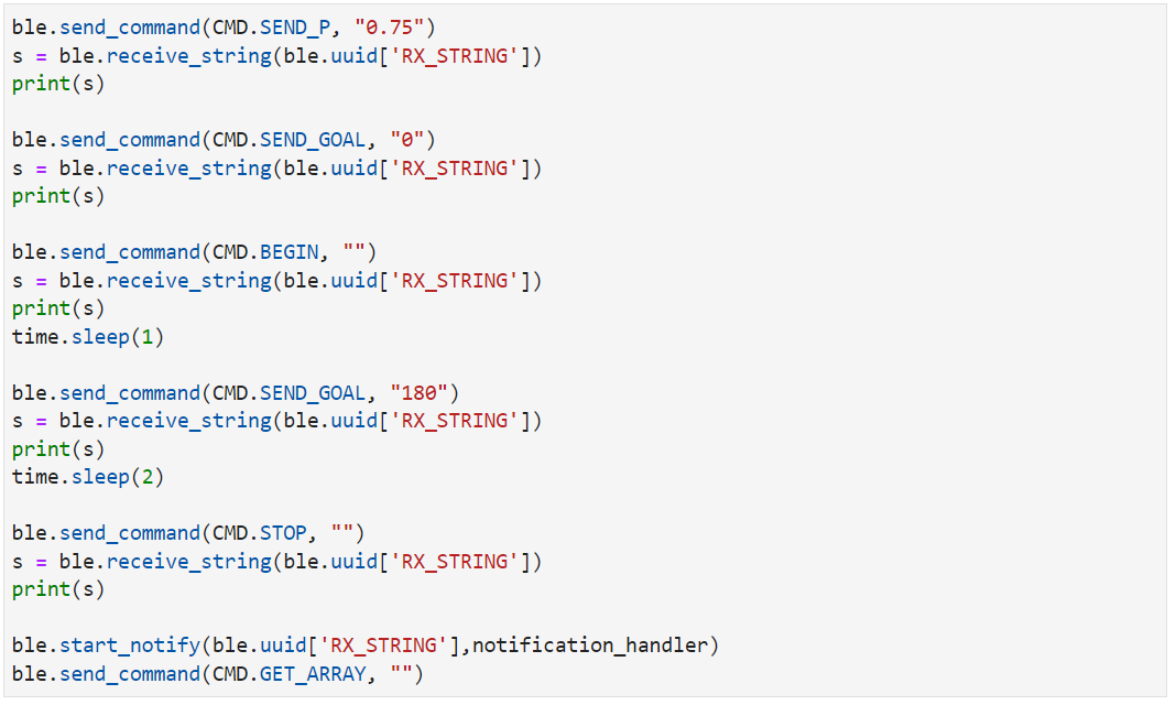
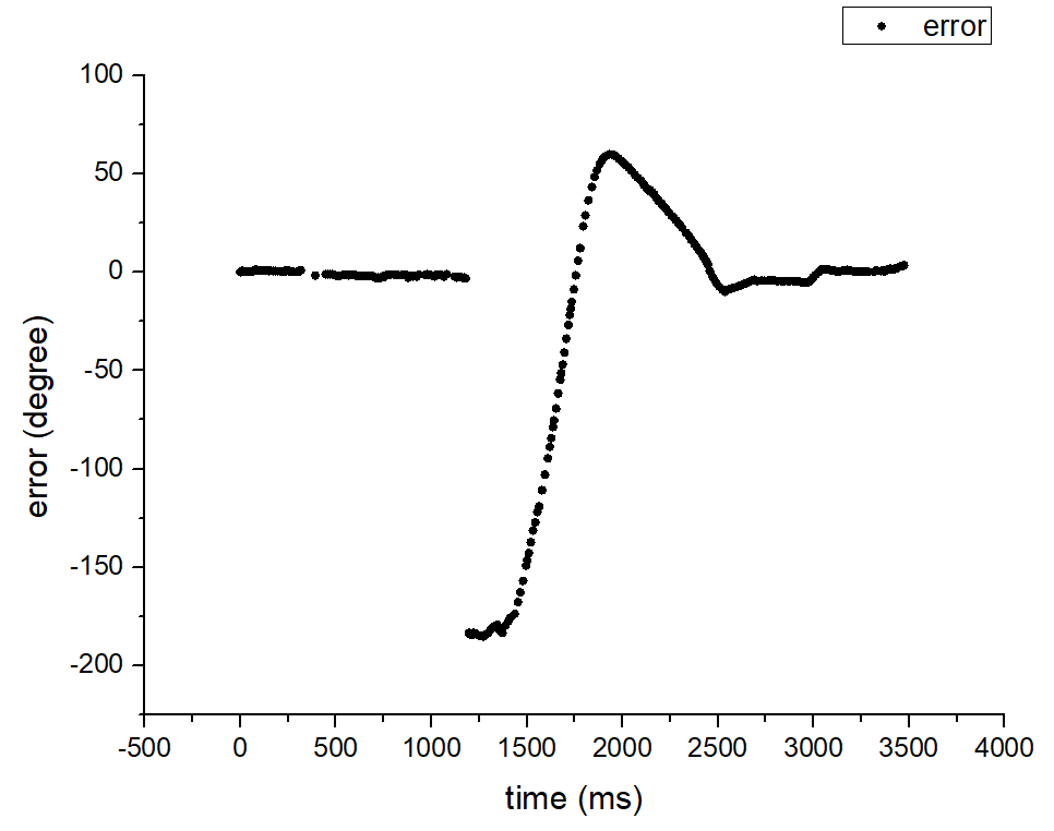
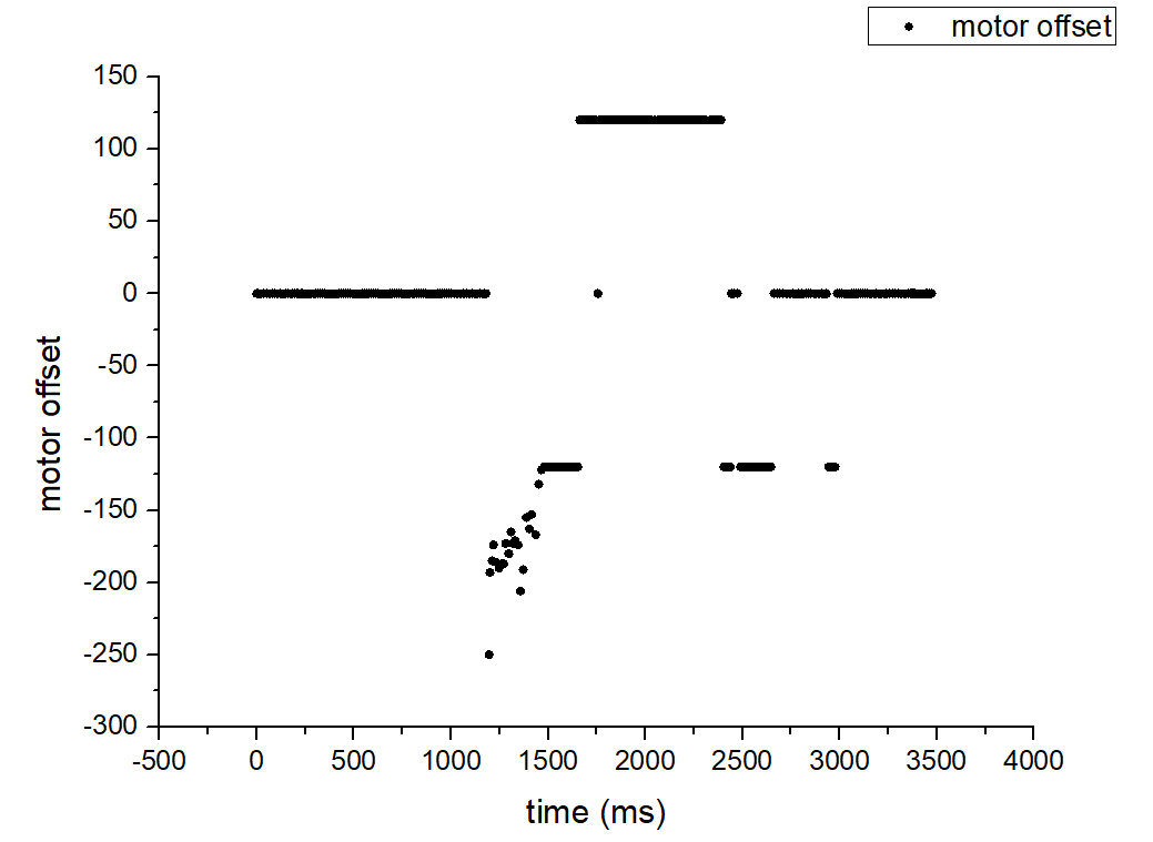
In the jupyter notebook, I used the following code to send commands and get debugging data. The set orientation is zero at the beginning and the car will move forward for one second. Then the setpoint will be changed to 180 degrees by the command. The car will stop after two seconds and receive the debugging data arrays.
ICM_20948_fss_t myFSS; // This uses a "Full Scale Settings" structure that can contain values for all configurable sensors
myFSS.g = dps1000; // (ICM_20948_GYRO_CONFIG_1_FS_SEL_e)
myICM.setFullScale((ICM_20948_Internal_Acc | ICM_20948_Internal_Gyr), myFSS);
